This page contains affiliate links. If you purchase through them we may earn a small commission at no extra cost to you. Learn more
Series vs Parallel Battery Configurations
The fundamentals
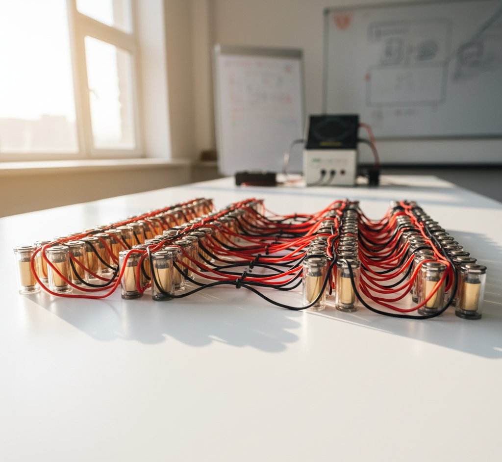
Series connection
Connecting cells positive-to-negative in a chain. Like stacking batteries end to end in a torch.
Effect: Voltages add up. Capacity (Ah) stays the same.
Example: 4 x 3.2V 100Ah LFP cells in series = 12.8V, 100Ah (1,280Wh)
Parallel connection
Connecting all positives together and all negatives together. Like putting batteries side by side.
Effect: Capacity (Ah) adds up. Voltage stays the same.
Example: 4 x 3.2V 100Ah LFP cells in parallel = 3.2V, 400Ah (1,280Wh)
Series-parallel (the common approach)
Most battery packs use both: series strings to reach the required voltage, then multiple strings in parallel for more capacity.
Notation: XS YP where X = cells in series, Y = parallel strings.
Example: 16S 2P using 3.2V 100Ah LFP cells:
- 16 cells in series = 51.2V nominal
- 2 parallel strings = 200Ah
- Total: 51.2V x 200Ah = 10,240Wh (10.24kWh)
Configurations for UK home solar storage
The 48V standard
Most UK hybrid inverters (GivEnergy, SunSynk, Solis, Fox ESS, Growatt) use a 48V nominal battery bus. This means your battery pack needs to provide approximately 48–52V nominal, which corresponds to:
LFP (LiFePO4): 16 cells in series (16S) — 16 x 3.2V = 51.2V nominal NMC: 13 cells in series (13S) — 13 x 3.7V = 48.1V nominal
LFP in 16S configuration is the standard for UK DIY solar batteries.
Common configurations
| Configuration | Nominal voltage | Capacity (100Ah cells) | Total energy |
|---|---|---|---|
| 16S 1P | 51.2V | 100Ah | 5.12 kWh |
| 16S 2P | 51.2V | 200Ah | 10.24 kWh |
| 16S 3P | 51.2V | 300Ah | 15.36 kWh |
| 16S 1P (280Ah cells) | 51.2V | 280Ah | 14.34 kWh |
For most UK homes, 16S 1P with 280Ah cells (14.3kWh) or 16S 1P with 100Ah cells (5.1kWh) are the most common DIY configurations.
Series connections in detail
Rules for series strings
- All cells must be the same chemistry — never mix LFP with NMC in the same string
- All cells should have similar capacity — grade and match cells before assembly (see our capacity testing guide)
- A BMS is mandatory — it monitors each cell's voltage and prevents overcharge/over-discharge of individual cells
- The weakest cell limits the string — if one cell has 90Ah capacity and the rest have 100Ah, the string is limited to 90Ah usable
Voltage ranges
For a 16S LFP pack:
| State | Cell voltage | Pack voltage |
|---|---|---|
| Fully charged | 3.65V | 58.4V |
| Nominal | 3.2V | 51.2V |
| Fully discharged | 2.5V | 40V |
| Typical operating range | 2.8–3.5V | 44.8–56V |
Your inverter must accept this voltage range. Most 48V hybrid inverters operate within 40–60V battery input, which matches the 16S LFP range perfectly.
Cell balancing is critical in series
In a series string, cells gradually drift apart in voltage due to slight manufacturing differences and varying self-discharge rates. Without balancing, some cells get overcharged while others are undercharged — reducing capacity and creating safety risks. Your BMS handles active or passive balancing to keep all cells within a few millivolts of each other. This is one of the most important functions of the BMS.
Parallel connections in detail
Rules for parallel strings
- Match cell capacity closely — parallel cells should be within 5% capacity of each other
- Match cell voltage before connecting — cells at different voltages will rush current between them when first connected. Pre-charge all cells to within 0.1V before paralleling.
- Use adequate wiring — parallel connections carry full string current; size cables accordingly
- Fuse each parallel string — if one string develops a short circuit, the fuse prevents other strings from feeding into the fault
Methods of paralleling
Cell-level parallel (before series): Connect individual cells in parallel first, then wire the parallel groups in series. This is the standard approach for cylindrical cell packs (e.g., 16S 4P using 21700 cells).
String-level parallel (after series): Build complete series strings, then connect the strings in parallel. This is common for prismatic cell packs (e.g., two 16S strings paralleled).
Both methods achieve the same result electrically. Cell-level parallel is slightly more balanced; string-level parallel is simpler to build and troubleshoot.
Pre-charge before paralleling
When connecting two battery strings in parallel, ensure their voltages are within 0.1V of each other. If one string is at 52V and another at 48V, connecting them will cause a surge of current as the higher-voltage string charges the lower one. This surge can blow fuses, damage cells, or cause sparks. Use a resistor (10–50 ohm, appropriately rated) temporarily in the connection path to limit initial current, then remove it once voltages equalise.
BMS requirements for different configurations
16S 1P (single string)
The simplest BMS requirement. A standard 16S BMS monitors all 16 cell groups (which are each a single cell).
- Passive balancing BMS (£20–£50) — bleeds excess charge from high cells through resistors. Adequate for well-matched cells.
- Active balancing BMS (£50–£150) — transfers energy from high cells to low cells. More efficient, recommended for second-life cells with wider capacity spread.
16S 2P+ (parallel strings)
For parallel configurations, you have two options:
-
Single BMS after paralleling — one BMS monitors the parallel groups (each group is 2+ cells in parallel). Simpler, cheaper, but can't detect individual cell faults within a parallel group.
-
BMS per string — each parallel string has its own BMS, with the strings paralleled at the output. More expensive but better fault isolation.
For most DIY home builds, a single BMS after paralleling is sufficient and simpler.
Wiring and safety
Cable sizing
Current = Power / Voltage. For a 5kW inverter on a 48V system:
Current = 5,000W / 48V = 104A maximum
At 104A, you need substantial cabling:
- Minimum 25mm² cable for short runs (under 2m)
- 35mm² or 50mm² for longer runs or continuous high current
- Use flexible welding cable or marine-grade battery cable
- Crimp terminals with hydraulic crimpers for reliable connections
Fusing
Every battery pack needs a main fuse between the battery and inverter:
- Size: 1.25–1.5x the maximum expected current (e.g., 125–150A for a 5kW/48V system)
- Type: Class T, ANL, or MEGA fuse rated for DC voltage
- Voltage rating: Must exceed your battery's maximum voltage (60V+ for a 16S LFP pack)
- Location: As close to the battery positive terminal as possible
Practical build order
- Test and grade all cells (see capacity testing guide)
- Sort cells into matched groups for series strings
- Assemble series connections using appropriate method (bolted bus bars for prismatic, spot welding for cylindrical)
- Install BMS — connect balance leads to each cell group in order
- If paralleling: pre-charge strings to matching voltage, then connect parallel with pre-charge resistor
- Install main fuse on positive output
- Test the complete pack — charge and discharge through BMS, verify all protections work
- Connect to inverter — configure inverter for correct battery type and voltage range
Share this article
Stay informed
Get free solar updates direct to your inbox
Related reading

Repurposing EV Batteries for Home Storage
Using second-life EV batteries for home solar storage in the UK. Sourcing, testing, safety considerations, and whether DIY repurposing is worth the effort.

Spot Welding vs Compression Fittings for Battery Packs
Comparing spot welding and compression fittings for connecting cells in DIY battery packs. Pros, cons, equipment costs, and which method suits home solar storage.
Battery Capacity Testing: Equipment and Methods
How to test the actual capacity of solar battery cells and modules. Equipment needed, testing methods, and how to assess second-life EV battery health.

Switch to Octopus Energy
Get 50 credit when you switch. We get 50 too — win-win.
What does this mean for YOUR home?
Design your perfect solar setup in under 3 minutes. Free, no sign-up required.
Build Your Solar System