This page contains affiliate links. If you purchase through them we may earn a small commission at no extra cost to you. Learn more
Battery CAN Bus & RS485 Protocols: Making Batteries Talk to Inverters
Why does this matter?
Your hybrid inverter needs to know the state of your battery. Specifically, it needs:
- State of Charge (SoC) — how full is the battery?
- Cell voltages — are any cells too high or too low?
- Temperature — is it safe to charge/discharge?
- Charge/discharge limits — what current can the battery accept right now?
- Alarms and warnings — is anything wrong?
Without communication, the inverter can only measure the battery's terminal voltage and make rough guesses. A 51.2V LiFePO4 pack sits between 48V (empty) and 54.4V (full), but the voltage curve is very flat in the middle — a pack at 30% SoC and one at 70% SoC might only differ by 1V. Voltage-only mode leads to overcharging, undercharging, and premature BMS cutoffs.
With proper CAN bus or RS485 communication, the BMS tells the inverter exactly what's happening inside the pack. The inverter adjusts its behaviour accordingly — tapering charge current as cells approach full, backing off discharge when any cell gets low, and stopping entirely if temperature is out of range.
CAN bus explained
CAN (Controller Area Network) bus is a communication standard originally developed for the automotive industry. It's robust, fast, and designed to work reliably in electrically noisy environments — which makes it ideal for battery-inverter communication.
How it works
CAN bus uses two wires (CAN_H and CAN_L) that carry differential signals. Data is sent in frames, each with an identifier (ID) and up to 8 bytes of payload. The battery BMS broadcasts data frames at regular intervals (typically every 100ms–1s), and the inverter reads them.
In practice, CAN bus communication between batteries and inverters uses one of several "profiles" — essentially agreed-upon message formats. These profiles define which CAN IDs carry which data.
Common CAN profiles
Pylontech protocol — the most widely supported. Originally developed by Pylontech, it's become a de facto standard. Many inverter manufacturers support "Pylontech-compatible" batteries. The JK BMS, Seplos BMS, and most Chinese rack batteries offer a Pylontech-compatible CAN profile.
SMA protocol — used by SMA inverters. Different message IDs and data format from Pylontech.
Victron protocol — Victron uses its own CAN profile (via VE.Can or CAN bus BMS port). The JK BMS supports this natively.
GivEnergy protocol — GivEnergy inverters support Pylontech protocol and their own variant. Fogstar Drift batteries ship with a GivEnergy profile pre-configured.
Physical connection
CAN bus is typically carried over an RJ45 (Ethernet-style) cable between the BMS and inverter. However, the pin assignments vary between manufacturers:
| Pin | Pylontech standard | Some JK BMS | Victron |
|---|---|---|---|
| 4 | CAN_H | CAN_H | CAN_H |
| 5 | CAN_L | CAN_L | CAN_L |
| 7 | GND | GND | GND |
Most of the time, a standard straight-through Ethernet cable works. But always verify pin assignments in both the BMS and inverter documentation before connecting.
Pin assignments are not standardised
Despite both devices using RJ45 connectors, the CAN bus pin assignments are NOT standardised across manufacturers. Connecting a cable between two devices with different pin mappings won't usually cause damage (CAN bus is differential and reasonably tolerant), but communication won't work. Check both device manuals and, if in doubt, make a custom cable with verified pinouts.
RS485 explained
RS485 is an older serial communication standard. It uses two wires (A and B) for differential signalling, similar to CAN bus, but the protocol layer is different. RS485 is typically used with Modbus RTU — a request-response protocol where the inverter polls the BMS for data.
CAN bus vs RS485
| Aspect | CAN bus | RS485 (Modbus) |
|---|---|---|
| Speed | 250kbps–500kbps typical | 9600–115200 baud |
| Update rate | 100ms–1s | 1–5s typical |
| Communication model | Broadcast (BMS pushes data) | Poll-response (inverter requests data) |
| Wiring | 2 wires + GND | 2 wires + GND |
| Noise immunity | Excellent | Good |
| Inverter support | Most modern inverters | Most inverters |
| BMS support | JK, Seplos, some Daly | JK, JBD (limited), Daly |
RS485 works fine for home battery systems. The slower update rate doesn't meaningfully affect performance — your battery state doesn't change that fast. The main practical difference is that CAN bus is more likely to work out of the box with predefined profiles, while RS485/Modbus often requires manual register configuration.
Voltage-only mode (fallback)
If you can't get CAN bus or RS485 working — or if your BMS doesn't support either — you can run in voltage-only mode. The inverter charges and discharges based solely on battery terminal voltage.
This works, but with limitations:
- SoC display on the inverter will be inaccurate (voltage curve is flat)
- No cell-level protection — the inverter doesn't know if one cell is struggling
- Charge current won't taper intelligently — higher risk of BMS cutoffs
- No temperature-based protection from the inverter side
Voltage-only mode is acceptable for simple setups but is the last resort for a proper grid-tied system.
Practical setup: JK BMS + GivEnergy inverter

This is the most common DIY combination in the UK. Here's the setup process:
- Install the JK CAN bus expansion board (if not pre-installed)
- Set the CAN protocol to "Pylontech" in the JK BMS app (via Bluetooth)
- Connect an RJ45 cable from the JK BMS CAN port to the GivEnergy inverter's battery communication port
- Set the GivEnergy inverter to "Pylontech" battery type in the inverter settings
- Verify communication — the inverter should show battery SoC, voltage, current, and temperature within a few seconds
If it doesn't work first time:
- Check the RJ45 pin assignments (GivEnergy uses pins 4/5 for CAN_H/CAN_L)
- Try a different CAN baud rate (usually 500kbps)
- Check the JK BMS firmware version — some older versions had CAN bus bugs
- Look for a 120Ω termination resistor requirement (some setups need one at each end of the CAN bus)
The 120Ω termination resistor
CAN bus requires 120Ω termination resistors at each end of the bus. Some BMS units and inverters have built-in termination; others don't. If communication is unreliable (intermittent dropouts, corrupted data), try adding a 120Ω resistor across CAN_H and CAN_L at the inverter end. A standard 120Ω ¼W through-hole resistor pushed into the back of an RJ45 connector works in a pinch.
Practical setup: JK BMS + Victron MultiPlus-II
Victron uses a different approach. The MultiPlus-II connects to a GX device (Cerbo GX or similar), which acts as the system brain. The battery CAN bus connects to the GX device, not the inverter directly.
- Set the JK BMS CAN protocol to "Victron" (or the compatible profile for your firmware version)
- Connect the CAN cable from the JK BMS to the Cerbo GX BMS-Can port
- Configure the Cerbo GX to recognise the battery (Device list → Battery)
- Verify — the Victron VRM portal should show full battery data
Victron's system is more flexible and better documented than most, but the extra GX device adds £200–£300 to the system cost.

Troubleshooting communication issues
Communication failures between batteries and inverters are the single most common headache in DIY battery builds. A systematic approach:
- Verify physical connection — correct cable, correct pins, secure connectors
- Check protocol match — both devices must use the same protocol (Pylontech, SMA, etc.)
- Check baud rate — CAN bus baud rate must match (typically 500kbps)
- Check termination — add 120Ω if in doubt
- Check firmware — update both BMS and inverter firmware to latest stable versions
- Check power — some BMS boards need the battery connected and powered on before CAN bus initialises
- Use a USB-CAN adapter — for advanced debugging, a £15 USB-CAN adapter and free software (like SavvyCAN) lets you see exactly what's on the CAN bus
Most communication issues resolve at steps 1–3. The UK DIY solar forums (particularly on Facebook and DIY Solar Forum) have extensive threads on specific BMS + inverter combinations — search before you ask.
The most popular inverter for DIY builds with CAN bus battery communication is the GivEnergy hybrid. Here's what we'd recommend:
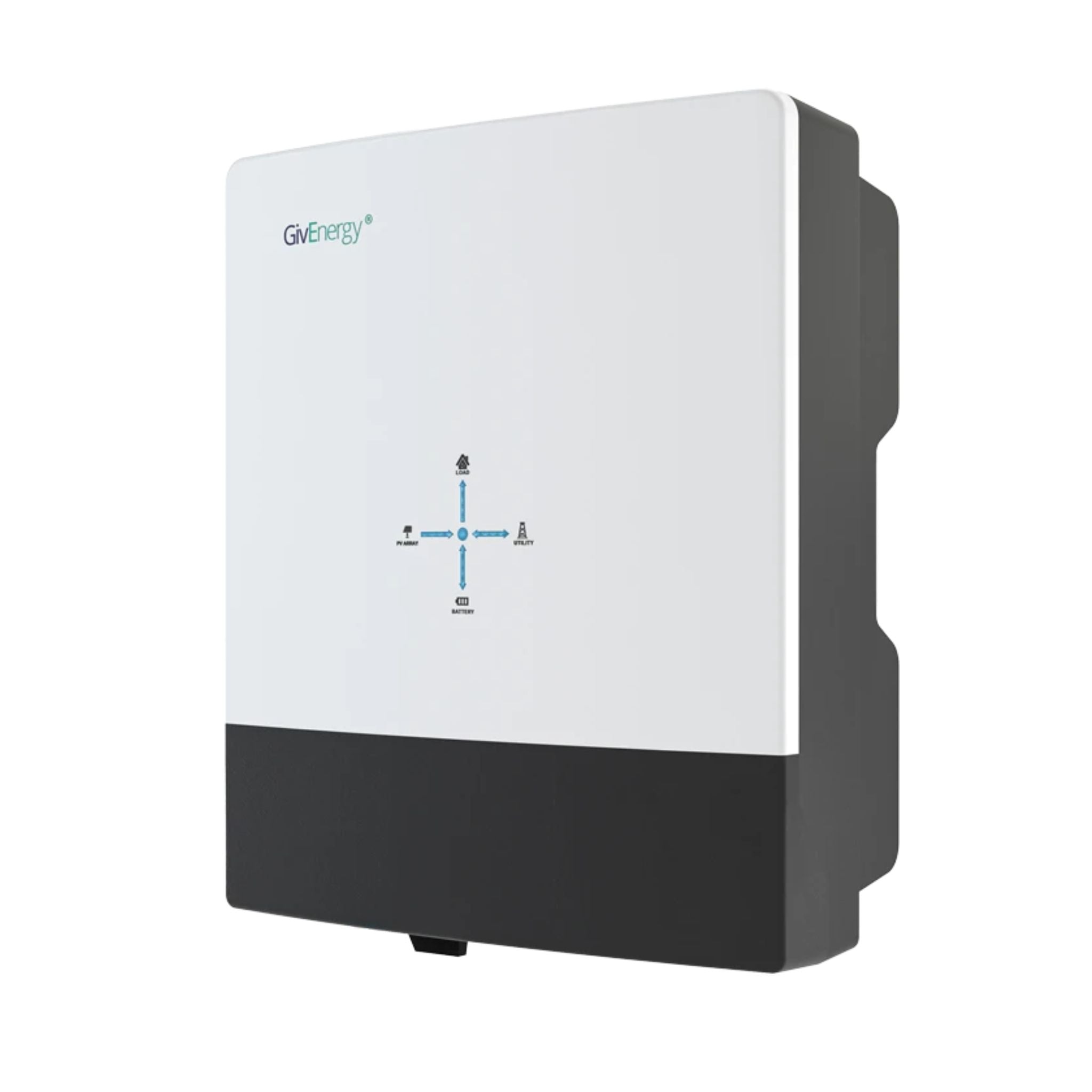
GivEnergy All-in-One 5kW Hybrid Inverter
£1,2005
7.5
2
48V
Affiliate link — we may earn a small commission at no extra cost to you
For a pre-built battery module with proven CAN bus compatibility, the Fogstar Seplos kit is the go-to:
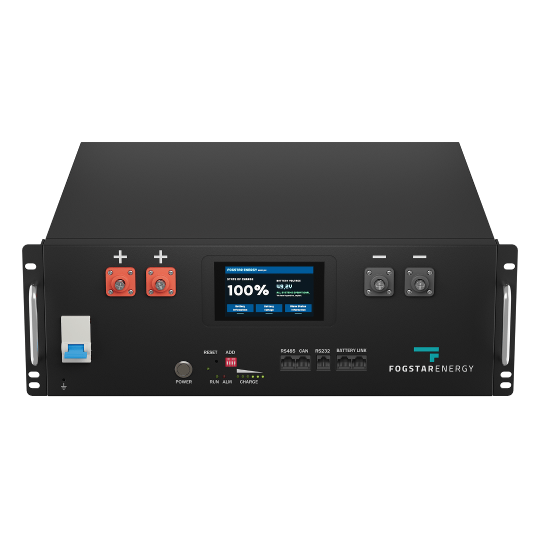
Fogstar Drift 5.12kWh LiFePO4 Battery
£1,5005.12
5
LFP
6000
Affiliate link — we may earn a small commission at no extra cost to you
Share this article
OVO has carefully selected trusted teams across the UK to install solar panels and heat pumps. Enjoy the personal touch of a local expert with the peace of mind of a household name.
Affiliate link — we may earn a small commission at no extra cost to you
Stay informed
Get free solar updates direct to your inbox
Related reading
BMS Comparison: JK vs JBD vs Daly for DIY Solar Batteries
Comparing the three most popular BMS options for UK DIY LiFePO4 battery builds — JK, JBD, and Daly. Features, pricing, and which to choose in 2026.
DIY Battery Storage in the UK: Complete Beginner's Guide
A practical guide to building your own DIY solar battery storage system in the UK — costs, legality, components, and whether it's actually worth it in 2026.
Solar Inverters Explained: Types, Sizing, and Real-World Limits
String, micro, and hybrid inverters explained clearly — plus the critical G98/G99 threshold at 3.68kW and what it means for what you can run simultaneously.

Switch to Octopus Energy
Get 50 credit when you switch. We get 50 too — win-win.
What does this mean for YOUR home?
Design your perfect solar setup in under 3 minutes. Free, no sign-up required.
Build Your Solar System