This page contains affiliate links. If you purchase through them we may earn a small commission at no extra cost to you. Learn more
DIY Battery Wiring & Fusing: Cable Sizing, Fuse Selection, and Safety
Why wiring matters more than you think
Your battery cells might be excellent. Your BMS might be perfectly configured. Your inverter might be top-tier. But if the wires connecting them are undersized, poorly terminated, or unfused, none of that matters.
DC wiring faults are the primary cause of fires in DIY battery installations. Unlike AC circuits (which pass through zero 100 times per second, helping to extinguish arcs), DC arcs are sustained and intensely hot. A loose DC connection at 50V carrying 80A will arc-weld itself, melt insulation, and potentially ignite surrounding materials.
This guide covers the essentials. It is not a substitute for BS 7671 or professional electrical training, but it will help you understand the requirements and avoid the common mistakes.
Cable sizing
The fundamental rule
Size cables for the maximum fault current your BMS will allow, not your expected typical load.
If your BMS has a 100A overcurrent cutoff, your cables must safely carry 100A continuously. The BMS takes a finite time (typically 100ms–1s) to react to overcurrent, and during that time, the full current flows through the cable.
DC cable sizing table
For single-core flexible DC cables (tri-rated or equivalent) at 48V:
| Max current | Minimum cable size | Voltage drop per metre (at max current) |
|---|---|---|
| 50A | 10mm² | 0.18V |
| 75A | 16mm² | 0.12V |
| 100A | 25mm² | 0.07V |
| 150A | 35mm² | 0.05V |
| 200A | 50mm² | 0.04V |
These are for cables in free air at 30°C ambient. If cables are bundled, enclosed, or in warm environments, derate accordingly (typically 20–30% reduction in current capacity).
Cable run length
Voltage drop matters on longer cable runs. At 48V, every volt lost in the cable is approximately 2% of your system voltage. Keep total cable length (positive + negative combined) under 3 metres where possible. For longer runs, go up one cable size.
Cable type
Use tri-rated cable (BS 6231) or H07V-K flexible cable for internal battery connections. For runs between the battery enclosure and inverter, use SY cable or equivalent with appropriate outer sheath for mechanical protection.
Do NOT use:
- Standard mains cable (designed for AC, not suitable for DC fault currents)
- Automotive cable (not rated for continuous high current in enclosed installations)
- Speaker cable, lamp flex, or anything else from a DIY store
DC and AC cable are NOT interchangeable
Cables rated for AC use may have insulation that degrades under sustained DC conditions. DC arcs are more sustained and hotter than AC arcs. Always use cables specifically rated for DC service or tri-rated cables that carry both AC and DC ratings.
Fuse selection
Why fuses are non-negotiable
A fully charged 16S LiFePO4 pack at 54.4V with 280Ah cells can deliver a peak fault current of 5,000A+ into a dead short circuit. Without a fuse, this current flows until something melts, catches fire, or the cells are destroyed.
A properly rated DC fuse interrupts the fault in milliseconds.
Fuse types for battery systems
Class T fuses — the gold standard for battery protection. Fast-acting, designed for DC, available in ratings from 50A to 400A at voltages up to 170VDC. Commonly used in marine and renewable energy applications.
NH-style fuses (BS88) — industrial-grade fuse links rated for DC. Available in very high current and voltage ratings. More robust than Class T but physically larger.
MIDI fuses — compact DC fuses used in automotive and small-scale renewable systems. Available up to 200A at 58VDC. A reasonable option for smaller DIY builds.
NOT suitable:
- Standard AC cartridge fuses — may not break a DC arc
- Automotive blade fuses — not rated for sustained high current or the voltage
- MCBs (miniature circuit breakers) designed for AC — DC breaking capacity is typically much lower than the AC rating
Fuse sizing
The fuse rating should be:
- Above the maximum expected operating current (so it doesn't nuisance-trip)
- Below the cable's continuous current rating (so the fuse protects the cable)
- Below the BMS overcurrent setting (so the fuse is the last line of defence, not the first)
Example for a 100A BMS system with 25mm² cable:
- Cable rating: 110A (25mm² in free air)
- Suitable fuse: 100A or 110A Class T
- BMS overcurrent: 100A (electronic, faster than fuse)
- The BMS catches normal overcurrent events; the fuse catches catastrophic shorts that might overwhelm the BMS
Fuse placement
The fuse must be within 300mm of the battery positive terminal. This is the critical rule. Every millimetre of unfused cable between the battery and the fuse is a potential fault point with no protection.
In practice: bolt the fuse holder directly to the battery positive bus bar or within 300mm via heavy-gauge cable.
DC isolator switches
Purpose
A DC isolator (disconnect switch) allows you to safely disconnect the battery from the inverter for maintenance, fault investigation, or emergency disconnection.
Requirements
- Rated for DC at your system voltage (at least 60VDC for a 48V system)
- Current rating equal to or above the fuse rating
- Load-break rated — must be able to interrupt current under load, not just in a de-energised circuit
- Lockable — so you can lock it open during maintenance
Popular options:
- Schneider iSW — widely available, DC-rated versions available
- ABB OT series — industrial DC disconnect switches
- Eaton/Bussmann — combined fuse/isolator units
Place the isolator between the fuse and the inverter. The sequence from battery to inverter should be: Battery → Fuse → Isolator → Inverter
Combined fuse-isolator units
Bussmann and other manufacturers make combined units that include both a DC fuse and an isolator switch in a single housing. These save space and simplify wiring. The MRBF (Marine Rated Battery Fuse) series is popular in the DIY solar community — compact, DC-rated, and available with isolator handles.
Circuit design

Basic single-battery circuit
Battery (+) → Fuse (within 300mm) → Isolator → Inverter DC+
Battery (-) → Inverter DC-
The negative cable typically runs direct (unfused) from battery to inverter. Some installations include a shunt (current sensor) in the negative line for monitoring.
Parallel battery circuit
When paralleling multiple battery modules:
Battery 1 (+) → Fuse → Common positive bus bar → Isolator → Inverter DC+
Battery 2 (+) → Fuse → Common positive bus bar ↗
Battery 1 (-) → Common negative bus bar → Inverter DC-
Battery 2 (-) → Common negative bus bar ↗
Each parallel battery must have its own fuse. If one battery develops an internal short, the other batteries will feed current into it. Individual fuses isolate the fault.
Use equal-length cables from each battery to the common bus bar. Unequal cable lengths create unequal resistance, leading to current imbalance between batteries.
Termination and connections
Crimping
All cable terminations should use properly crimped copper lugs — hydraulic crimpers produce the most reliable joints. Hand-squeeze crimpers are adequate for cables up to 16mm² but marginal for 25mm²+.
After crimping, apply heat-shrink tubing over the lug barrel for insulation and strain relief.
Torque
All bolted connections must be torqued to specification:
| Connection | Typical torque |
|---|---|
| Bus bar to cell terminal | 10 Nm |
| Fuse terminal | Per manufacturer spec (usually 5–8 Nm) |
| Inverter DC terminal | Per manufacturer spec |
| Cable lug to bus bar | 10–12 Nm |
Use a torque wrench. Over-tightening can strip threads or crack terminals. Under-tightening creates resistance and heat.
Inspection
After completing all wiring:
- Visual check — all connections tight, no exposed copper, no cable strain
- Torque check — re-verify all connections with torque wrench
- Continuity test — verify end-to-end continuity of each cable run
- Insulation test — verify no short circuits between positive and negative
- Voltage check — measure voltage at the inverter terminals to confirm correct polarity
Common mistakes
- Using automotive blade fuses — not rated for the voltage or sustained current
- Fuse too far from battery — the unfused section is your weakest link
- No fuse at all — "the BMS will protect it" is not a valid safety strategy. The BMS is electronic and can fail.
- Undersized cables "because I only draw 30A normally" — fault currents don't care about your normal load
- Poor crimps — a bad crimp is worse than no crimp; it creates a hidden high-resistance joint
- Mixing cable sizes — the thinnest cable in the circuit limits the whole circuit
- No isolator — you need to be able to disconnect the battery safely without touching live terminals
Get the wiring right, and your DIY battery system will operate safely for decades. Get it wrong, and you've built a fire hazard. This is the one area of a DIY build where there's no room for "good enough."
For a battery module with pre-integrated wiring and fusing that eliminates many DIY wiring risks:
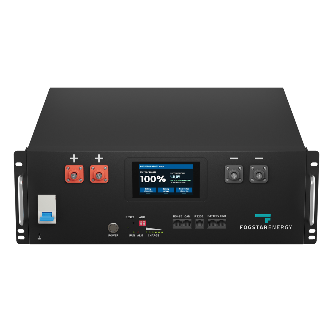
Fogstar Drift 5.12kWh LiFePO4 Battery
£1,5005.12
5
LFP
6000
Affiliate link — we may earn a small commission at no extra cost to you
The GivEnergy All-in-One comes fully wired and fused from the factory — the safest option if wiring complexity concerns you:
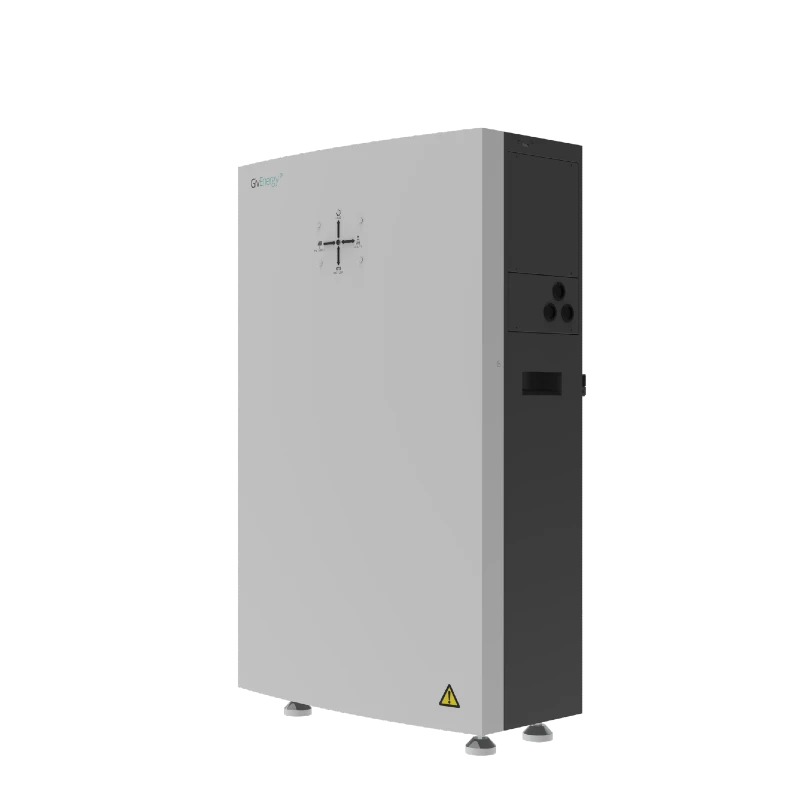
GivEnergy All-in-One 9.5kWh Battery
£5,5009.5
8.6
LFP
6000
Affiliate link — we may earn a small commission at no extra cost to you
Share this article
OVO has carefully selected trusted teams across the UK to install solar panels and heat pumps. Enjoy the personal touch of a local expert with the peace of mind of a household name.
Affiliate link — we may earn a small commission at no extra cost to you
Stay informed
Get free solar updates direct to your inbox
Related reading
DIY Battery Storage in the UK: Complete Beginner's Guide
A practical guide to building your own DIY solar battery storage system in the UK — costs, legality, components, and whether it's actually worth it in 2026.

Battery Thermal Safety: Preventing Fires in DIY Solar Storage
Thermal safety for DIY LiFePO4 solar batteries in the UK — fire risks, prevention measures, ventilation, and what to do if something goes wrong.
DIY Battery Enclosures: Housing Your Solar Battery Safely
How to build or choose a battery enclosure for DIY LiFePO4 solar storage in the UK — ventilation, fire ratings, materials, and placement guidance.

Switch to Octopus Energy
Get 50 credit when you switch. We get 50 too — win-win.
What does this mean for YOUR home?
Design your perfect solar setup in under 3 minutes. Free, no sign-up required.
Build Your Solar System